Hardware
Thirty-seven nodes are available in R2lab to provide a modern testbed infra structure. The nodes are distributed in a grid layout and are customizable, allowing great variety of experimentation scenarios.
Full control and access to bare metal
The nodes are totally open and users can install any software stack they need
The testbed is yours
The testbed is reservable as a whole.
Once they have booked the testbed, registered users can ssh into faraday.inria.fr,
and from there control all the resources in the testbed.
You are thus in full control of all the radio traffic in the chamber.
The nodes are yours
Also you can load your operating system of choice on any node. From that point you can ssh-access all nodes with administration privileges, and configure the available resources - nodes, SDRs and phones - to create a rich experimental environment.
Methodology
Experimental scenarios can be created using standard tools. We also provide tutorials, and python libraries that can optionnally help you efficiently orchestrate the complete experimental workflow, from deployment to data collection.
All nodes
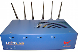
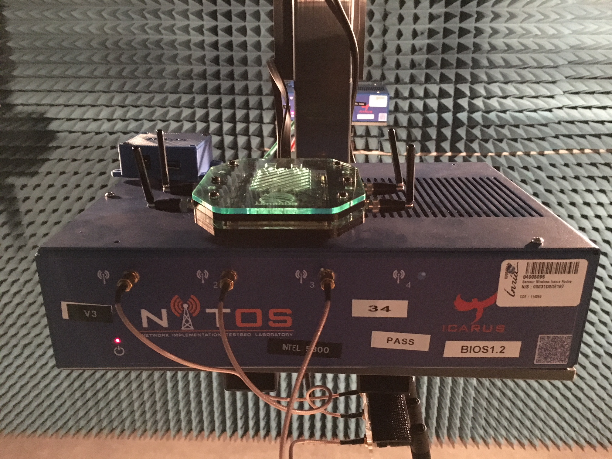
32 nodes based on Nitos X50 are currently available and feature
- State of the art motherboard
- CPU Intel Core i7-2600 processor
- 8GB RAM
- 240 GB SSD
- 2 Wireless Interfaces, dedicated to experimentation, 3 antennas each :
- one Atheros 802.11 93xx a/b/g/n - exposed as
atheros - and one Intel 5300 - exposed as
intel
- one Atheros 802.11 93xx a/b/g/n - exposed as
- 3 wired interfaces used for :
- remote power and reset management (not visible from linux)
control, used by the testbed management framework for providing access - reachable from the gateway as e.g.fit02orfit34data, dedicated to experimentation - known as e.g.data04ordata12
Four miniPC nodes :
called pc01/pc02/pc03/pc04 installed instead of the Nitos X50 nodes at location fit04/fit06/fit13/fit30, respectively.
connected via USB3 to either USRP B210 devices or 5G RG530F Quectel devices and attached to the control wired interface.
represented as square boxes in the R2lab dynamic map, they have an independent numerotation than fit nodes.
to switch them on or off or to check their current state, use the rhubarbe commands rhubarbe pdu on|off|status pc01|pc02|pc03|pc04. Note that the devices attached to them (i.e., usrp01/usrp02/rg530f-01/rg530f-02) are also controllable through the same rhubarbe pdu commands.
Hardware specifications :
- pc01/pc02 are UM690 (Micro Computer (HK)) miniPC 16-core AMD Ryzen 9 6900HX with Radeon Graphics, 32 GB RAM.
- pc03/pc04 are UP-APL03 (AAEON) miniPC 4-core Intel Pentium CPU N4200 @ 1.10GHz, 8 GB RAM.
5G Phones
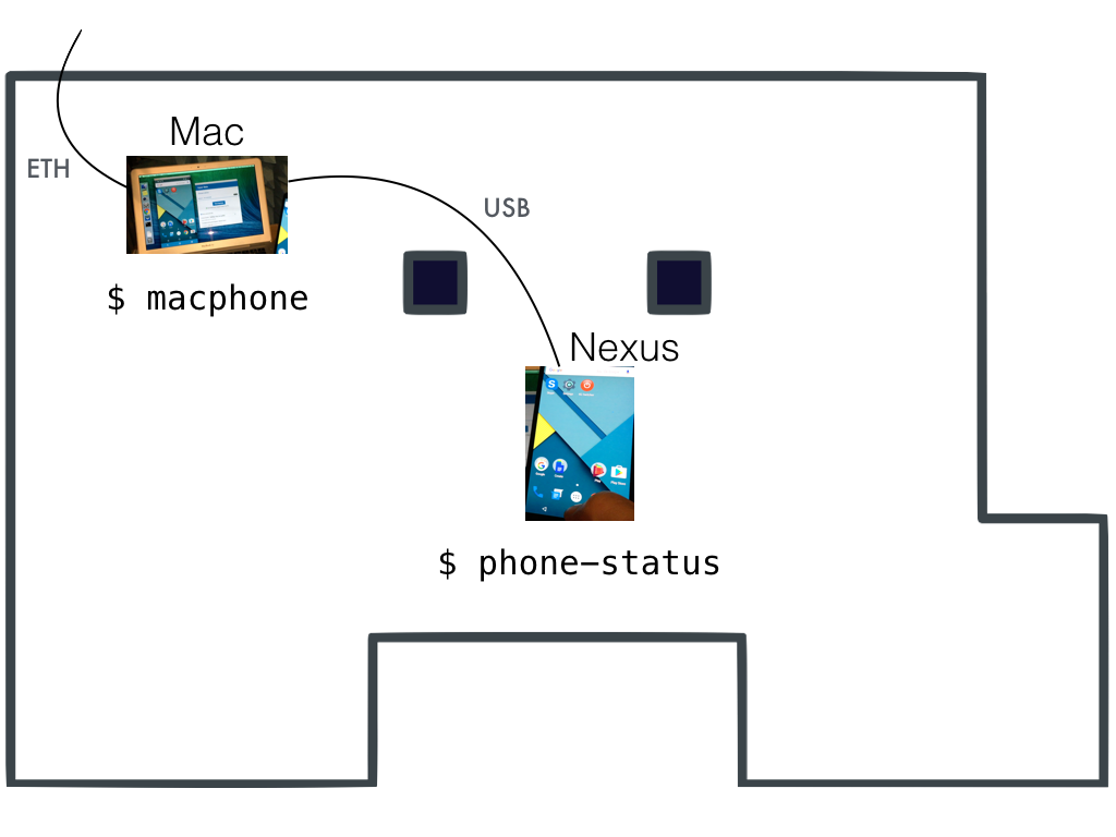
The testbed offers a couple of commercial smartphones right inside the chamber:
HUAWEI P40 Pro attached to
macphone1, with SIM IMSI: <001010000000001>
(called phone1)Google Pixel 7 attached to
macphone2, with SIM IMSI: <001010000000002>
(called phone2)
Note that:
- Each phone is reachable through a Mac (that also sits in the room) that has its wireless card physically disabled, and that has a USB cable to the phone.
- The mac can be reached from the gateway as e.g.,
ssh tester@macphone1
(or themacphone1convenience shell shortcut) - Once logged in the Mac you can use convenience helpers to manage the
phone
(typehelpfor details), or useadbmanually. - The mac can also be managed using apple screen sharing tools
(VNC-compliant),
pointing directly atfaraday-macphone1.inria.fr - You will find more details about controlling the phone in the tutorials section.
USRP devices
Some nodes are equipped with USRP devices from ETTUS to run SDR-based experiments such as spectrum analyzer or 4G/5G OpenAirInterface scenarios. All these devices can be remotely-controlled through the ust/uon/uoff utilities.
Currently, our deployment features the following types of USRP devices :
- USRP B210,
- USRP B205mini,
- USRP N210,
- USRP 2, and
- USRP 1 (see detailed mapping in the table below).
Make sure to read the additional notes below that cover some specifics of these devices.
Also, two more powerful USRP devices are currently available:
- USRP N320
- USRP N300
Each one is connected through 2x10Gbps SFP+ fibers to our SophiaNode cluster. The oai5g-rru scripts demonstrate how to use those devices (e.g. using-R N300option) to set up a 5G demo with OAI5G microfunctions on R2lab.
Important notes on SDR devices
Please note the following specifics about the additional SDR devices:
the following table shows in the sdr columns the type of the attached SDR or
noneif none is installed.Depending on the SDR device, one or two Rx/Tx channels may be available. The antennas attached to each channel are specified as follows: 900M for omni-directional 5dBi antennas, operating on 800-900MHz; 2-5G for dual-band 5dBi omni-directional antennas, operating on both 2.4GHz and 5GHz; and Dup-eNB or Dup-UE if a duplexer is used.
Warning: the
N210andusrp2models use an Ethernet connection to link to the node. This means that on those nodes, thedatawired interface is not available, as the hardware interface is wired into the USRP device.
Duplexers
Some USRP devices, like the B210, have their Tx and Rx SMA
connectors very close to one another. For that reason some have
a device named a duplexer band 7 [specs] [pict].
The settings used in our deployed duplexers match the frequencies used in our default configuration for OpenAirInterface. That is to say, it is assumed that
- Downlink (eNB to UE) uses frequency 2.66 GHz (duplexers are set to the 2.62-2.69 GHz range)
- Uplink (UE to eNB) uses frequency 2.54 GHz (duplexers are set to the 2.50-2.57 GHz range)
In the sdr antennas column below, devices are
tagged as either none, Dup-UE or Dup-eNB.
With the above assumptions, these tags can be interpreted as follows:
none: no duplexer is attachedDup-UE: to transmits on the uplink and receive on the downlink; hence typically this setup can be used to scramble the uplinkDup-eNB: conversely, this node is fit to scramble the downlink
Lime SDR devices
Here are the detailed specifications for the LimeSDR devices deployed in the chamber (see table below for the details on which nodes host such devices)
- RF Transceiver: Lime Microsystems LMS7002M MIMO FPRF (Datasheet)
- FPGA: Altera Cyclone IV EP4CE40F23 - also compatible with EP4CE30F23
- Memory: 256 MBytes DDR2 SDRAM
- Oscillator: Rakon RPT7050A @30.72MHz (Datasheet)
- Continuous frequency range: 100 kHz – 3.8 GHz
- Bandwidth: 61.44 MHz
- RF connection: 10 U.FL connectors (6 RX, 4 TX)
- Power Output (CW): up to 10 dBm
- Multiplexing: 2x2 MIMO
- Dimensions: 100 mm x 60 mm
- Plus: "What makes LimeSDR interesting is that it is using Snappy Ubuntu Core as a sort of app store. Developers can make code available, and end-users can easily download and install that code."
AW2S 5G Remote Radio Heads (RRH) / Remote Radio Units (RRUs)
Two 5G RUs are available:
- JAGUAR 2T2R RUs (CPRI Split 8), IBUmax 50MHz, MIMO 2x2
- PANTHER 4T4R RUs (CPRI Split 8), IBUmax 100MHz, MIMO 4x4
As for USRP N3XX devices, each AW2S RU is connected through either 2x10Gbps or 2x25Gbps fibers to our SophiaNode cluster. The same oai5g-rru scripts can be used with e.g., -R jaguar option to demonstrate how to use a AW2S RU to set up a 5G demo using OAI5G microfunctions on R2lab.
Note that the N300 USRP device and the JAGUAR RU are connected to HUBER+SUHNER SENCITY® OCCHIO MIMO 2x2 5G omnidirectional antennas, while the N320 USRP device and the PANTHER RU use HUBER+SUHNER SENCITY® OCCHIO MIMO 4x4 5G omnidirectional antennas.
Huawei LTE Stick
The testbed currently includes 1 Huawei LTE stick:
- One Huawei E3372 sticks on node fit26
(with SIM IMSI <208950000000015>).
Bluetooth 4.2/5.0 Low Energy (BLE) devices
- Two RedBearLab BLE Nano Kit v2 devicess on nodes fit01 anf fit03, loaned by Eurecom.
5G Quectel RM 500Q-GL modules connected via USB3 to fit nodes
Six 5G Quectel modules with M.2 to USB3.0 adapter enclosure for Quectel RM 500Q-GL modules using specific kits (composed of M.2/USB3 interface and 4 antennas):
- One attached to fit07 with SIM IMSI: <001010000000003>
- One attached to fit09 with SIM IMSI: <001010000000004>
- One attached to fit18 with SIM IMSI: <001010000000005>
- One attached to fit31 with SIM IMSI: <208950000000010>
- One attached to fit32 with SIM IMSI: <208950000000011>
- One attached to fit34 with SIM IMSI: <208950000000009>
5G Quectel RM 500Q-GL on Raspberry Pi4
Three 5G modules composed of a Raspberry Pi 4B device with a hat used to connect a Quectel RM 500Q-GL module using specific kits (composed of M.2/USB3 interface and 4 antennas):
- qhat01 with SIM IMSI: <001010000000006>
- qhat02 with SIM IMSI: <001010000000007>
- qhat03 with SIM IMSI: <001010000000008>
R5G Quectel RM 520N-GL on Raspberry Pi4
Two 5G Quectel modules composed of a Raspberry Pi 4B device with a hat used to connect a Quectel RM 520N-GL module using specific kits (composed of M.2/USB3 interface and 4 antennas):
- qhat10 with SIM IMSI: <001010000000013>
- qhat11 with SIM IMSI: <001010000000014>
5G Quectel RG255C-GL on Raspberry Pi4
Four 5G Quectel RedCap modules composed of a Raspberry Pi 4B device with a hat used to connect a Quectel RG255C-GL module using specific kits (composed of M.2/USB3 interface and 2 antennas). Note that these 4 modules do not support the MBIM mode, use the QMI mode instead.
- qhat20 with SIM IMSI: <001010000000009>
- qhat21 with SIM IMSI: <001010000000010>
- qhat22 with SIM IMSI: <001010000000011>
- qhat23 with SIM IMSI: <001010000000012>
All the 9 Raspberry Pi4 devices are connected via an Ethernet port to the control wired interface.
5G Quectel RG-530F on Quectel 5GDM01 Evaluation board kit
Two 5G RG-530F Quectel modules for FR2 band to be used with the Liteon gNB:
- integrated in Quectel 5GDM01-EV EVB kit.
- rg530f-01 with SIM IMSI: <001010000000015> connected via USB3 to pc03 miniPC.
- rg530f-02 with SIM IMSI: <001010000000016> connected via USB3 to pc04 miniPC.
Nodes detailed information
Clicking in the header will focus on nodes that have a USRP device
Nodes health
The testbed routinely runs a thorough raincheck procedure, to make sure that all is in order.
Stay away from nodes that show up behind a big red circle, as this means that the node is not available.